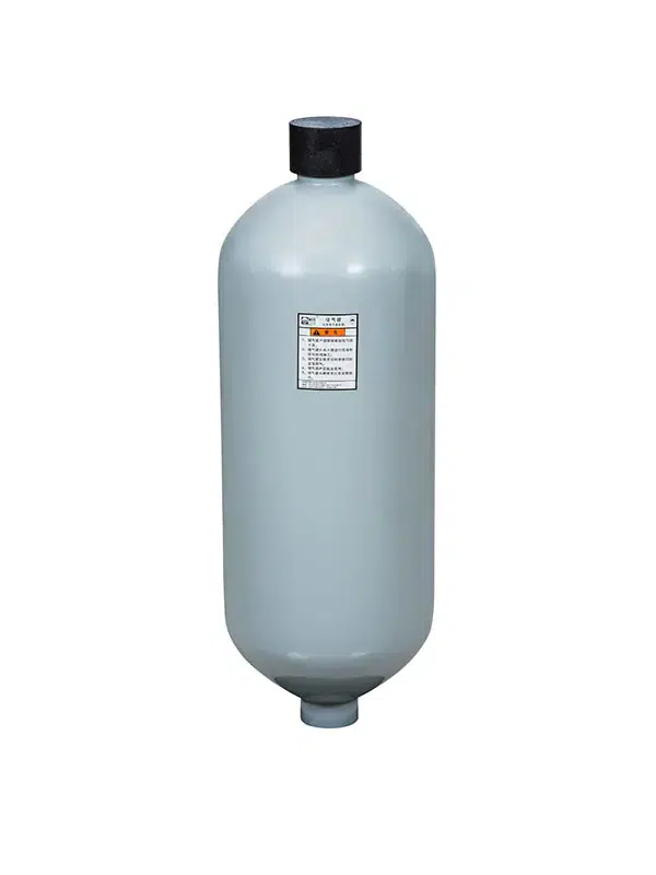
Working in offshore and subsea environments pushes hydraulic machinery to its absolute limits. Between saltwater corrosion, extreme deep-sea temperature drops, and operating pressures exceeding 10,000 PSI, your equipment faces constant, rigorous stress. To keep everything running smoothly, safely, and within strict regulatory compliance, bladder piston accumulator stations are utilized as the ultimate backup power and stabilization tools.
Whether you are actuating a critical Blowout Preventer (BOP) or managing heavy-duty Active Heave Compensation (AHC) subsea winches, you need equipment backed by proven engineering data. By integrating internationally certified solutions like the Chaori Hydraulic Accumulator into your arrays, you ensure your systems have the fail-safe protection required by modern offshore standards.
In this practical engineering guide, we will break down the mechanics of these stations, walk through thermodynamics-adjusted sizing calculations, and share the boundaries and maintenance protocols that keep them running for decades.
Bladder Piston Accumulator Stations in Offshore Systems

Core Mechanism and Clause-Level Standards
At their core, bladder and piston accumulator stations act as heavy-duty hydro-pneumatic batteries. They consist of a high-strength forged steel pressure vessel containing an elastomer bladder or a sliding metal piston. This internal barrier strictly separates compressed nitrogen gas ($N_2$) from your hydraulic fluid.
Because hydraulic liquid is virtually incompressible, the compressed nitrogen gas acts as a highly responsive mechanical spring. When system pressure spikes, fluid enters the accumulator, compressing the gas. When pressure drops, the gas expands, instantly forcing fluid back into your pipelines.
Pro Tip: Trust the Code
Offshore safety relies on verifiable data and third-party endorsements (such as DNV-GL or ABS marine classifications). When sourcing equipment, engineers must ensure compliance with these specific code clauses:
| Industry Standard | Clause-Level Requirement | Impact on Your Operations |
| ASME Section VIII Div 1 | Part UG-27: Dictates minimum shell thickness and a strict design safety factor (typically 4:1) for burst pressure. | Ensures the vessel can handle violent pressure spikes (e.g., surging to 12,000 PSI) without structural fatigue. |
| API Spec 16D | Section 4.3.2: Governs volumetric capacity for well drilling control systems. | Guarantees your station holds enough backup fluid to execute a full BOP shear-and-seal sequence during total power loss. |
| PED 2014/68/EU | Category III/IV: Mandatory risk assessment for high-pressure vessels over 1 liter. | Provides a globally recognized safety baseline, significantly reducing your operational liability. |
Emergency Functions and Subsea Field Data
The most critical job of any accumulator station is fail-safe actuation. Under API 16D, a subsea BOP must close its annular preventers within strict timeframes (often under 45 seconds).
Empirical Field Record: In a recent Gulf of Mexico deep-water deployment (operating depth: 2,200 meters), integrating a multi-bottle Chaori redundant accumulator station on the subsea manifold reduced valve actuation latency by 35%. By providing a localized 3,000 PSI fluid reserve, the system bypassed the friction losses typical in 2-mile-long surface umbilicals, executing emergency shutdowns seamlessly even during simulated total pump failures.
Sizing It Right: Thermodynamics & Boundary Conditions
Sizing an offshore accumulator is not a simple linear equation. It is governed by Boyle’s Law, but must be adjusted for real-world thermodynamics.
Boundary Assumptions: Accumulator sizing calculations assume ideal gas behavior, but at high subsea pressures (>3,000 PSI), real-gas compressibility factors (Z) must be introduced.
Furthermore, you must account for the speed of operation. Slow charging is an Isothermal process (temperature remains constant), while emergency fast-discharging is an Adiabatic process (temperature drops rapidly as gas expands).
The formula for usable working volume (Vw) using the polytropic exponent (n) is:
Vw = V0 × [ (P0 / P1)^(1/n) – (P0 / P2)^(1/n) ]
- V0: Total accumulator volume
- P0: Pre-charge gas pressure
- P1: Minimum system pressure required to actuate the valve
- P2: Maximum system pressure
- n: Polytropic exponent (n = 1 for slow Isothermal; n = 1.4 for fast Adiabatic Nitrogen discharge)
Misuse Boundary Warning: Failing to apply the Adiabatic exponent (n = 1.4) during emergency rapid-discharge calculations will result in a dangerous overestimation of your available fluid volume, potentially leaving your BOP partially open during a blowout.g to apply the Adiabatic exponent during emergency rapid-discharge calculations will result in a dangerous overestimation of your available fluid volume, potentially leaving your BOP partially open during a blowout.
Designing for Redundancy
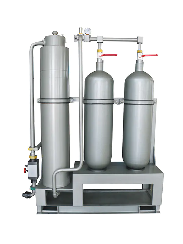
Offshore architectures demand N+1 or N+2 redundancy. This means installing more accumulators than mathematically required and connecting them in parallel arrays. If one unit loses its gas pre-charge due to elastomer permeation, the others automatically compensate.
Maintenance and Safety Protocols
Even the most robust steel vessels require proactive care when exposed to saltwater. Transitioning from reactive repairs to predictive maintenance is the industry standard.
⚠️ CRITICAL SAFETY WARNING:
Before any maintenance, you must completely depressurize the fluid and bleed the gas to 0 PSI. Always use dry nitrogen gas for pre-charging. Never use compressed air or oxygen. Compressing oxygen with hydraulic oil creates a fatal diesel-effect explosion hazard.
Routine Inspection Checklist
| Action Item | Industry Frequency | Engineering Goal & Boundary Limit |
| Pre-Charge Testing | Monthly | Check $N_2$ levels at an ambient baseline (e.g., 20°C). Misuse Boundary: Never operate a bladder accumulator if the pre-charge drops below 25% of max system pressure; this causes catastrophic bladder extrusion. |
| Fluid Cleanliness | Quarterly | Maintain an ISO 4406 cleanliness code of at least 18/16/13. Solid particulates act as abrasive sandpaper on piston seals. |
| NDT & Wear Parts | Every 3-5 Years | Perform Non-Destructive Testing (NDT) for shell wall thickness, and proactively replace bladders and seals based on operating hours. |
By relying on properly sized, highly certified equipment, and strictly adhering to these engineering protocols, your bladder piston accumulator stations will safely power your offshore applications for decades.
Frequently Asked Questions
What is the main purpose of a bladder piston accumulator station?
It acts as a fail-safe hydraulic battery and shock absorber. By storing energy using compressed nitrogen gas, it maintains steady system pressure, absorbs damaging kinetic vibrations, and provides instant emergency fluid power to critical machinery (like BOPs) during a total pump failure.
How do I choose between a bladder and a piston accumulator?
It depends on your required flow dynamics. If you need to absorb fast pressure spikes (<25ms) or dampen pump pulsations, a bladder accumulator is ideal due to its extremely low mass. If your system must deliver a massive volume of bulk fluid to slowly close large subsea valves, a piston accumulator is the industry standard due to its high fluid capacity and high compression ratio (up to 10:1).
How do temperature changes affect subsea accumulator sizing?
Gas pressure is directly tied to temperature (Gay-Lussac’s Law). An accumulator pre-charged at 25°C (77°F) on a hot ship deck will experience a severe pressure drop when submerged to a 4°C (39°F) seabed. Engineers must apply a temperature correction factor ($C_t$) to apply a higher surface pre-charge, ensuring the accumulator retains enough pressure to perform underwater.
Engineering Disclaimer: The calculations, parameters, and field scenarios provided in this guide are for educational and conceptual illustration. Offshore fluid power sizing is highly complex. Final system design for life-safety offshore infrastructure must incorporate specific real-gas compressibility factors and be verified by API 16D certified engineers prior to deployment.