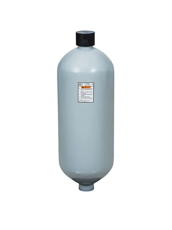

A bladder accumulator stores hydraulic energy using a flexible rubber bladder pre-charged with compressed nitrogen inside a steel shell. Hydraulic fluid enters the shell and compresses the bladder, storing energy. When system pressure drops, the gas expands and forces the hydraulic fluid back into the circuit. This design provides rapid response and effective shock absorption.
Key Takeaways
- Bladder accumulators store energy by compressing a nitrogen-filled rubber bladder with hydraulic fluid.
- When pressure drops, the accumulator releases stored energy quickly, providing fast response and effective shock absorption.
- Check nitrogen pre-charge pressure regularly to maintain performance and prevent gas loss through the bladder.
- Pre-charge pressure is typically set to 80% of the minimum allowable system pressure for bladder accumulators.
- Material selection (NBR, Butyl, EPR, FKM) depends on fluid type and temperature.
- Bladder accumulators are well-suited for high-cycle, shock-absorption, and fast-response applications.
Key Parts of a Bladder Accumulator
The Bladder and Steel Shell
The rubber bladder separates the compressed nitrogen gas from the hydraulic fluid. Bladder-type accumulators use a flexible, seamless rubber bladder inside a steel shell. Material choice affects service life and compatibility:
- Nitrile (NBR): Standard for most oil-based hydraulic fluids; operating range +5°F to +194°F.
- Butyl and EPR: Suitable for phosphate ester-based fluids.
- Fluoroelastomer (FKM/Viton): Withstands temperatures up to 350°F.
- Low-temperature Nitrile: Designed for environments as cold as -60°F.
Permeability varies by material; Nitrile generally has higher gas permeability than Butyl. Select the material that matches your fluid and temperature requirements.
The steel shell houses the bladder and acts as a pressure vessel. Manufacturers typically use high-strength, seamless chromium-molybdenum-carbon steel that meets ASME pressure vessel standards (e.g., ASME BPVC Section VIII Div. 1). Shells are pressure-tested at 1.5 times the operating pressure, and an authorized inspector applies the “U” stamp to certify compliance. A common design safety factor is 4:1 regarding burst pressure.
| Component | Typical Material Specification |
|---|---|
| Steel Shell | High-strength seamless chrome-moly carbon steel; ASME pressure vessel standards |
| Bladder | High-grade elastomer; standard Buna-N; options include Butyl, EPR, Viton |
Gas Valve and Fluid Port
The gas valve charges the bladder with nitrogen to a specific pre-charge pressure. This pressure determines response characteristics. The valve must seal tightly to prevent gas leakage over time. Inspect the gas valve regularly and recharge if needed.
The fluid port is the inlet and outlet for hydraulic fluid. Its design protects the bladder during high-flow operations.
How Bladder Accumulators Work: The Operational Cycle

Bladder accumulators undergo three stages:
Charging: Hydraulic fluid enters through the fluid port, compressing the nitrogen gas inside the bladder. This compression stores energy. For nitrogen (a diatomic gas), the process is often modeled as adiabatic, following pVγ=constant with γ≈1.4. The adiabatic curve is steeper than an isothermal curve, so pressure rise is more pronounced when temperature changes are considered.
Storage: The accumulator holds pressurized fluid. The compressed nitrogen maintains system pressure stability, and the bladder remains compressed, ready to release energy.
Discharge: When system pressure drops, the compressed gas expands, forcing stored fluid back into the hydraulic circuit. The lightweight bladder responds rapidly to pressure changes.
For volume compensation—such as emergency braking during power loss, supplementing pump flow, or maintaining constant system pressure—most manufacturers recommend setting the pre-charge pressure for bladder accumulators to 80% of the minimum allowable system pressure. For piston accumulators, a common recommendation is 100 psi below the minimum system pressure.
Pressure Ranges and Efficiency
Bladder accumulators are designed for high-pressure applications and are widely used in industrial hydraulic systems due to their rapid response. They serve four primary functions:
- Maintaining stable system pressure
- Storing and recovering energy
- Mitigating pressure spikes
- Absorbing shock
Efficiency in shock absorption depends on the application, pre-charge pressure, and system conditions. Manufacturers may report high absorption efficiency under specific test conditions; always confirm performance data for your operating parameters.
Bladder vs. Piston Accumulators

Advantages of Bladder Accumulators
Bladder-type accumulators are known for speed and efficiency. The lightweight rubber bladder reacts quickly to pressure fluctuations, providing excellent shock absorption. This makes them well-suited for high-cycle applications.
Piston-type accumulators use a heavy, free-floating piston instead of a rubber bladder. They still offer good response in most applications, but are generally slower and less effective for shock absorption than bladder accumulators.
| Accumulator Type | Response Time | Shock Absorption Effectiveness | Reason |
|---|---|---|---|
| Bladder | Fast | Highly effective | Lightweight flexible rubber bladder |
| Piston | Slower | Less effective for shock absorption | Heavier free-floating piston |
Bladder accumulator stations work best where fast response and good shock absorption are needed. Piston accumulators remain a good choice for other conditions, such as very high volumes or high cycle rates with different maintenance profiles.
Disadvantages and Maintenance
A primary issue with bladder accumulators: nitrogen slowly permeates the rubber bladder over time, causing pre-charge pressure to drop. Technicians should periodically check and replenish nitrogen. Simple pressure gauge checks during routine maintenance can prevent performance degradation.
Pre-charge inspection steps:
Record the date and pressure for future reference.
Isolate the accumulator from the system and relieve hydraulic pressure.
Connect a nitrogen pressure gauge to the gas valve.
Compare reading to the specified pre-charge pressure.
If low, recharge with nitrogen to the recommended pressure.
Choosing a Bladder Accumulator
When selecting an accumulator, consider:
- System pressure: Minimum and maximum operating pressures.
- Temperature range: Fluid and ambient temperatures.
- Fluid compatibility: Bladder material must match the hydraulic fluid.
- Required volume: Determine the volume needed for energy storage or shock absorption.
- Response time: Bladder accumulators are preferred for fast response.
- Certifications: Verify ASME “U” stamp or equivalent for pressure vessels.
Some manufacturers, such as Ningbo Chaori Hydraulic, offer bladder, piston, and diaphragm accumulators, as well as accumulator stations. Verify product-specific certifications and ratings for your application.
FAQ
How often should I check the nitrogen pre-charge?
Check periodically using a pressure gauge. Recharge to the recommended pre-charge pressure, often 80% of the minimum allowable system pressure. Frequency depends on the application and manufacturer’s guidance.
What causes a bladder accumulator to fail over time?
Nitrogen slowly permeates the rubber bladder, causing pre-charge pressure to drop. Selecting a lower-permeability bladder material, such as Butyl, can reduce gas loss.
Which applications suit bladder accumulators best?
Applications requiring rapid response and effective shock absorption, including high-frequency cyclic operations.
Can I use any bladder material with any hydraulic fluid?
No. Nitrile is standard for oil-based fluids; Butyl and EPR suit phosphate esters; FKM handles high temperatures. Always check compatibility.
What safety standards apply to bladder accumulators?
Pressure vessels often follow ASME BPVC Section VIII Div. 1 and carry a “U” stamp. Confirm local requirements and manufacturer certifications.