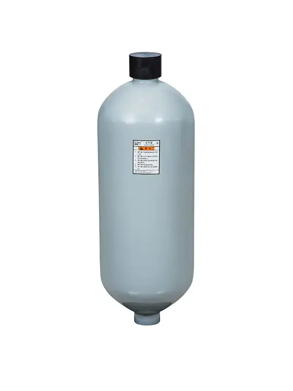

An aircraft hydraulic accumulator holds pressurized hydraulic fluid, keeping system pressure consistent while absorbing sudden hydraulic shocks. You can think of it as a rechargeable battery for your aircraft hydraulic circuit, built to store energy on demand. Most commercial airliners carry a minimum of two accumulators on‑board: one assigned to the main hydraulic system, and a second unit dedicated to emergency backup use. Its three core jobs are pressure stabilization, energy storage and shock dampening. In the sections below, we break down its internal parts, working cycle, common variants and routine maintenance tips.
Key Takeaways
- Aircraft accumulators store energy by compressing nitrogen gas, which maintains steady hydraulic pressure across the system.
- When the main hydraulic pump stops working, the accumulator delivers backup hydraulic power that allows pilots to extend the landing gear.
- Maintenance technicians must inspect the nitrogen pre‑charge pressure on a regular schedule to keep the accumulator operating correctly.
Aircraft Hydraulic Accumulator: Core Components

Every aircraft hydraulic accumulator shares a fundamental layout, with four major components working together to store energy and smooth‑out pressure swings. Understanding each component’s function makes the full operating cycle far easier to follow.
The Shell, Bladder, and Gas Charge
The shell is the heavy‑duty outer housing of the accumulator. This thick‑walled metal cylinder encloses all internal parts and withstands wide‑ranging high and low pressure cycles throughout flight. Accumulator shells are commonly manufactured from high‑strength steel or lightweight titanium alloy.
Inside the shell sits either a flexible bladder or a moving piston. This component forms a physical barrier between two different media. The bladder acts like an expandable rubber balloon, inflating and deflating in response to changing system pressure. Piston‑style accumulators rely on a sliding metal disc for separation. Both designs prevent nitrogen gas and hydraulic fluid from mixing together.
The pre‑charged gas is what actually stores potential energy. Nitrogen fills the chamber above the bladder or piston and behaves like a mechanical spring. As hydraulic fluid flows into the accumulator, it compresses the nitrogen gas, locking energy away. When hydraulic system pressure falls, the compressed nitrogen expands and pushes stored fluid back out into the circuit.
Manufacturers pressurize nitrogen to specified pre‑charge values. Standard industry pre‑charge settings fall between 1,200 psi and 3,000 psi. This gas level directly shapes how the accumulator reacts to system demand. A higher pre‑charge pressure creates a stiffer spring response, while a lower pre‑charge setting allows the unit to hold a larger volume of hydraulic fluid.
Nitrogen pre‑charge pressure heavily influences overall accumulator performance. Maintenance technicians must always match this pressure setting to the exact requirements of the aircraft hydraulic system.
The Fluid Port and System Connection
The fluid port creates the critical connection point between the accumulator and the rest of the hydraulic network. Hydraulic fluid flows in and out of the shell through this opening. The joint is secured with threaded fittings or bolt‑on flanges, and precision seals prevent fluid leakage at this high‑pressure connection.
This port hard‑wires the accumulator to the main pressure line, giving it the fastest‑possible reaction time to sudden pressure shifts. Whenever the hydraulic pump delivers more fluid than the system currently needs, the accumulator takes on the excess volume. When actuator demand outpaces pump output, the accumulator releases its stored fluid back into the system.
This connection also lets maintenance crews isolate the accumulator from the rest of the circuit. An integrated shut‑off valve allows technicians to service the unit safely. They can test nitrogen pressure or replace a worn bladder without draining the entire aircraft hydraulic system.
Fluid‑port sizing directly impacts real‑world performance. A larger‑diameter port enables faster fluid transfer, which becomes extremely important during emergency operations. An aircraft hydraulic accumulator must release its stored energy instantly the moment backup power is required. Every single component, from the outer shell to the fluid connection port, plays an essential part in this rapid response.
How the Hydraulic System Uses the Accumulator
The Charging and Discharging Cycle
Aircraft hydraulic accumulators continuously cycle between charging and discharging modes. During stable flight conditions, the hydraulic pump pushes fluid into the accumulator. This incoming fluid compresses the nitrogen gas trapped inside the shell. The compressed nitrogen holds potential energy, just like a tightly coiled spring ready to release force.
Once system pressure begins to drop, the cycle reverses. Nitrogen gas expands and forces stored hydraulic fluid back into the main pressure lines. This action stabilizes pressure for the complete hydraulic circuit. Accumulators react to pressure changes far quicker than any mechanical hydraulic pump.
This charge‑discharge loop repeats non‑stop for the duration of flight. While system‑wide fluid demand is low, the pump tops‑up the accumulator. During high‑demand periods, the accumulator supplements pump output. This shared workload reduces strain on the hydraulic pump and extends its service life. The accumulator also absorbs pressure spikes created when hydraulic actuators move rapidly.
The same charge‑discharge cycle delivers emergency backup power. Should the primary hydraulic pump fail completely, the accumulator releases its stored energy. This backup hydraulic supply gives pilots enough power to lower the landing gear or adjust flight‑control surfaces. An aircraft hydraulic accumulator can deliver this life‑saving power within seconds, buying flight‑crew time to troubleshoot faults or complete a safe landing.
Types of Accumulators and Their Applications
Different aircraft jobs need different accumulator designs. Each type has its own strengths for specific tasks.
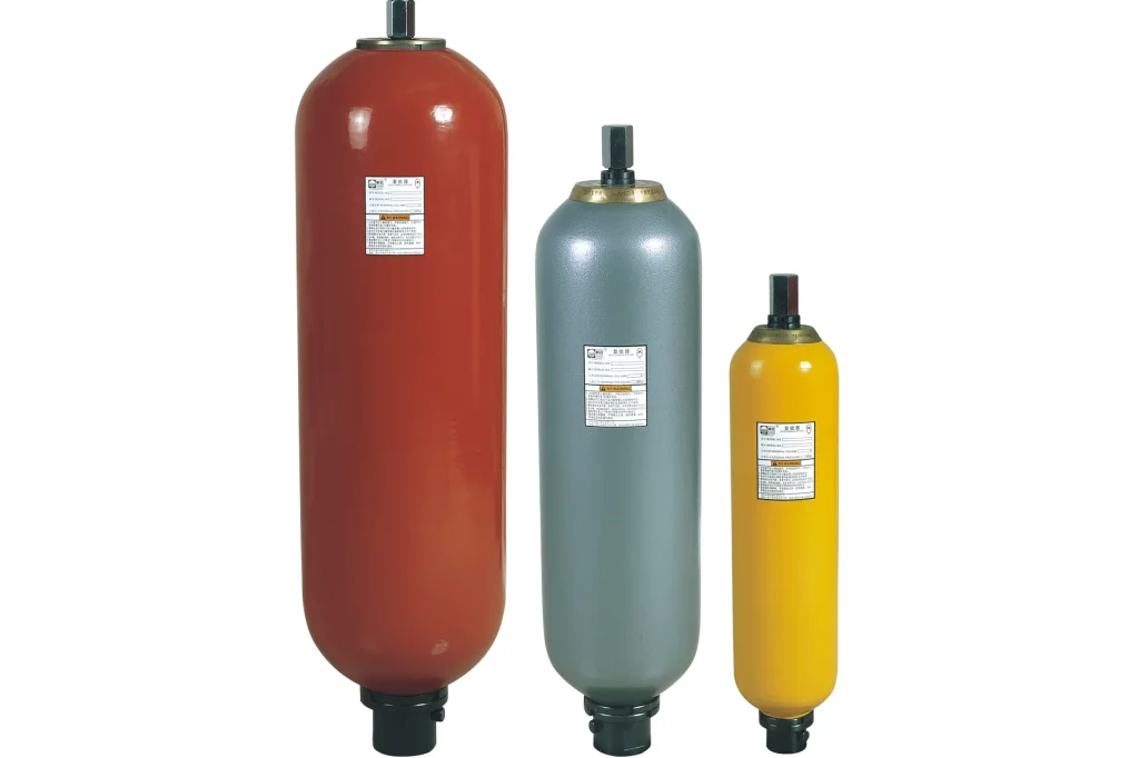
- Bladder accumulators shine in aerospace use. They respond fast thanks to great working efficiency. These units handle landing gear and braking systems with ease. Their energy storage keeps things smooth and steady under high-pressure loads.
- Piston accumulators fit precise energy control in smaller systems. They offer compact builds with strong sealing. Wind power pitch control systems often use this type.
- Diaphragm accumulators reduce vibration well. Their small size and sensitivity make them perfect for exact energy control in tight spots.
Companies like Chaori Hydraulic make these types for many industries. Their bladder accumulators manage high pressures and big flows for heavy jobs. Piston accumulators from the same maker serve wind power and precision gear markets. Diaphragm types work in systems that need vibration damping and accurate pressure control.
The right accumulator type depends on what the system needs. High-pressure aircraft systems pick bladder designs for quick response. Smaller auxiliary systems might use diaphragm types to save space. Each setup does the same core job: keeping pressure steady and storing energy.
The accumulator’s job goes beyond normal use. During pump failure, it becomes the main power source. This backup makes the aircraft hydraulic accumulator vital for flight safety. The stored hydraulic fluid gives the pressure needed for critical tasks until the crew restores normal operation.
The aircraft hydraulic accumulator stores energy, maintains pressure, and ensures safety. This hydraulic battery keeps the hydraulic system responsive and reliable. Stored hydraulic fluid provides emergency power during pump failure. The hydraulic system depends on this component daily. How might accumulators improve other industries? Consider their role beyond aviation.
FAQ
How often should an aircraft hydraulic accumulator be inspected?
Technicians check accumulators during regular aircraft maintenance. They verify nitrogen pre-charge pressure and look for fluid leaks. Most operators follow manufacturer guidelines, typically checking every 12 months or during scheduled overhauls.
What happens when the nitrogen pre-charge drops too low?
A low nitrogen charge reduces energy storage capacity. The hydraulic system loses its shock absorption ability. Pressure changes become more noticeable. The accumulator cannot deliver emergency power when needed. Regular pressure checks prevent this condition.
Can a faulty accumulator cause hydraulic system failure?
Yes. A failed accumulator leaves the hydraulic system without backup power. Pumps work harder and wear faster. Pressure spikes can damage sensitive parts. Pilots may lose emergency functions like landing gear extension during pump failure.