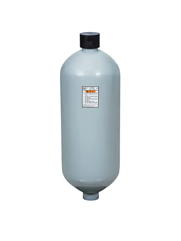
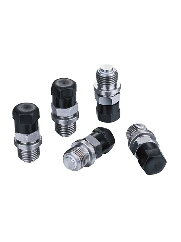
An accumulator valve controls hydraulic fluid flowing in and out of a hydro-pneumatic vessel. It regulates flow by comparing system pressure against the pre-charged nitrogen pressure inside the accumulator. When system pressure rises, nitrogen is compressed so the accumulator receives and stores hydraulic fluid. When pressure drops, nitrogen expands and pushes fluid back into the hydraulic circuit through the valve.
Key Takeaways
- Accumulator valves save liquid power by pressing nitrogen gas inside a metal tank.
- Inside check valves stop saved fluid from rushing backward into the main pump.
- Saved fluid pressure keeps machinery safe from sudden power outages and strong shock waves.
How the Accumulator Valve Regulates Flow

Fluid Inlet and Gas Compression
The accumulator valve manages fluid movement during the charging phase. Gas and hydraulic fluid remain fully separated inside the pressure vessel. Flexible bladders, sliding pistons or elastic diaphragms create a barrier between the two media. Fluid can only enter the chamber once system pressure exceeds the preset pre-charge level.
- Pre-Charge Pressure (P0) ≤ 0.9 × Minimum System Operating Pressure (P1)
- Hydraulic oil enters the chamber when system pressure surpasses P0.
- The incoming fluid compresses nitrogen gas to store hydraulic energy.
Rising pressure drives fluid into the vessel and compresses the nitrogen. System pumps continue feeding fluid throughout charging. Compressed nitrogen retains energy until pressure reaches the system upper limit.
Non-Return Check Valve Mechanism
An integrated non-return check valve directs fluid inflow during charging and stops trapped fluid from returning to the main pump. It relies on a self-tightening sealing structure. Reverse pressure pushes internal valve components harder against the seat. Greater backpressure creates a tighter seal and improves overall hydraulic accumulator performance.
An internal spring assembly governs valve opening and closing behaviour:
- Stiffer springs require higher cracking pressure to open.
- Sufficient spring force ensures rapid closure once flow ceases.
- Adjustable spring preload enables precise tuning of cracking pressure.
Manufacturers select high-grade materials for valve seats to withstand repeated pressure cycling. Hardened components reduce wear and support operating temperatures up to 500°C.
| Ball Material | Seat Material | Cycle Life Potential | Key Characteristics |
|---|---|---|---|
| 440C Stainless Steel | 316 Stainless Steel (polished) | 10-20 million cycles | Handles clean media and moderate pressure (≤5000 PSI). |
| Silicon Nitride Ceramic | Tungsten Carbide | 50+ million cycles | Provides highest cycle life for water applications (≤10,000 PSI). |
| 440C Stainless Steel | FKM (Viton) Elastomer | 20-30 million cycles | Offers chemical resistance under lower pressure (≤1500 PSI). |
| 440C Stainless Steel | Nylon/Delrin (POM) | 15-25 million cycles | Works well with water and mild chemicals (≤2000 PSI). |
| Silicon Carbide Ceramic | Silicon Carbide Ceramic | 50+ million cycles | Ideal for abrasive media under extreme pressure (≤15,000 PSI). |
Ceramic balls paired with tungsten carbide or ceramic seats deliver superior wear resistance. These combinations achieve over 50 million operating cycles without thermal deformation or compression failure commonly seen in plastic seats. Robust accumulator valve construction maintains circuit stability under harsh working conditions.
Operational Cycle of an Accumulator Valve

Controlled Energy Storage and Release
The working cycle begins when system pressure pushes fluid toward the valve inlet. Hydraulic accumulators capture surplus energy during low-demand periods. Compressed nitrogen inside the vessel forms an on-demand pressurised energy reserve. During peak load conditions, the accumulator rapidly releases stored energy to assist primary hydraulic pumps.
- Energy storage improves system efficiency, allowing designers to specify smaller pumps and electric motors.
- Pumps operate intermittently instead of continuously, lowering overall power consumption.
- Reserves deliver immediate backup pressure if main pumps fail unexpectedly.
Fluctuations from pump pulsation or rapid valve actuation create destructive pressure transients inside pipelines. The accumulator absorbs sudden pressure spikes and prevents pipeline damage.
Accumulator operation depends on the large difference in compressibility between gas and liquid. In bladder-type units, nitrogen compresses readily while hydraulic oil is nearly incompressible. Oil fills the vessel and charging initiates once pressure exceeds pre-charge level. The compressible gas volume acts as a buffer to absorb pressure fluctuations and shocks.
Consistent damping of pressure variations enables stable operation of hydraulic equipment through intensive industrial cycles.
System Pressure Reset and Relief
Before maintenance, technicians isolate fluid circuits using safety blocks supplied by Ningbo Chaori Hydraulic. Special nitrogen service kits safely test pre-charge pressure and support standard accumulator recharging procedures.
- Fully depressurise the main hydraulic circuit and confirm zero line pressure.
- Connect the pressure gauge from the nitrogen charging kit directly to the gas valve.
- Read static pre-charge pressure P0 via the service gauge.
- Verify measured gas pressure sits within 80–90% of the minimum working pressure.
- Slowly fill dry nitrogen from storage cylinders; avoid oxygen contamination.
- Inspect for gas leakage, reinstall the valve cap and restore fluid circuit operation.
Correct nitrogen maintenance prevents bladder damage and maintains balanced pressure inside the vessel. Accumulator valves fitted on heavy construction machinery and wind power equipment require periodic inspection. Industrial operators can source bulk safety components to sustain stable hydraulic pressure control.
| System or Regulation | Recommended Inspection Interval | Key Notes |
|---|---|---|
| Accumulator Precharge | Annual | Record precharge pressure values to spot bladder or diaphragm wear over time. |
| DOT-Regulated Pipelines (49 CFR Part 195) | Biannual (every 6 months) | Complete two yearly checks with no more than 15 months between tests. |
| Alternative Check Valve Systems | Varies (often 2-year cycles) | Testing timelines depend on local legal rules and daily machine operating settings. |
Regular accumulator maintenance prevents unplanned plant downtime. Routine inspections confirm proper valve seating and enable safe pressure relief during nitrogen refilling.
The accumulator valve operates in a continuous mechanical cycle. Fluid enters the vessel and compresses nitrogen; the check valve prevents reverse flow. When demand rises, expanding gas discharges stored fluid to counteract sudden pressure surges. Precise regulation protects pumps and enhances overall hydraulic system performance. Industrial machinery relies on accumulators to deliver consistent power during operation.
FAQ
How does nitrogen gas regulate hydraulic pressure?
Nitrogen gas squeezes inside the container whenever system pressure grows higher. The gas expands during pressure drops, pushing fluid back into the system to maintain stable continuous energy.
What occurs during accumulator charging?
Hydraulic fluid beats the pre-charged nitrogen force during accumulator charging. Fluid enters the container and compresses the gas, completing the primary system charging step efficiently.
Why does an accumulator need a check valve?
The integrated check valve stops pressurized fluid from flowing backward toward the pump. This valve locks fluid inside the accumulator until the system requires extra power.