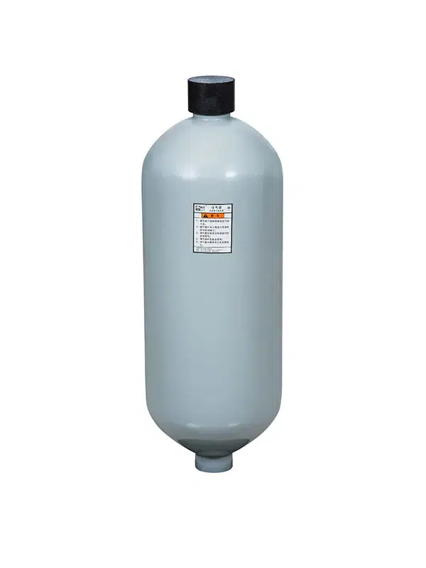
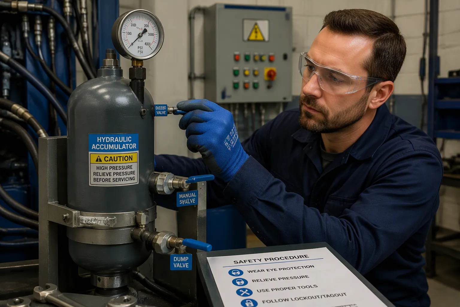
To safely release pressure from a hydraulic accumulator, technicians must first put on protective equipment and isolate the unit. They should then slowly open the pressure-relief valve while closely monitoring the pressure gauge until the reading drops to zero. The specific steps include donning protective gear, isolating the unit, slowly opening the pressure-relief valve, and observing the pressure gauge. Following the correct pressure-relief procedure helps effectively prevent personal injury and equipment damage.
Key Takeaways
- Before working on an accumulator, ensure you are wearing gloves, safety goggles, and protective clothing.
- Isolate the accumulator from the system by closing the shut-off valve, and disconnect and lock out the power source.
- Slowly open the pressure relief valve while monitoring the pressure gauge. Do not touch any connections until the pressure gauge reading has dropped to zero.
Preparation for Relieving Accumulator Pressure

Essential Safety Gear and Tools
Before releasing pressure or charging an accumulator, a thorough inspection must be conducted. First, identify the type of accumulator, as bladder-type accumulators and piston-type accumulators require different handling procedures. Next, check for leaks and address any potential leak points. Ensure that all valves are closed and that the shut-off valve is positioned for easy access.
Furthermore, verify that the system pressure has been reduced to zero, implement “Lockout/Tagout” (LOTO) procedures, and disconnect both hydraulic and electrical power sources. One critical rule must be strictly followed: never attempt to pre-charge an accumulator while the system is under pressure. Technicians must completely release system pressure before venting any nitrogen. Additionally, all work should be performed in a well-ventilated area to prevent the inhalation of gases. Setting the safety valve within a range of 2500–3000 psi ensures that system pressure remains at a safe level during normal operation.
Inspecting the Accumulator System
Before charging an accumulator, a thorough inspection must be conducted. First, identify the type of accumulator, as bladder-type and piston-type units require different handling procedures. Next, check for leaks and address any potential leak points. Ensure that all valves are closed and that the shut-off valve is positioned for easy access. Furthermore, verify that the system pressure has been reduced to zero, implement “Lockout/Tagout” (LOTO) procedures, and disconnect both hydraulic and electrical power sources.
One critical rule must be strictly followed: never attempt to pre-charge an accumulator while the system is under pressure. Technicians must completely release system pressure before venting any nitrogen. Additionally, all work should be performed in a well-ventilated area to prevent the inhalation of gases. Setting the safety valve within a range of 2500–3000 psi ensures that system pressure remains at a safe level during normal operation. By following these inspection protocols, safety is integrated into every task involving an accumulator.
Accumulator Pressure Relief Procedure
Isolating the Accumulator
The first step is isolation. Technicians must close the shut-off valve located between the accumulator and the pressurized circuit. Typically, a 90-degree full-bore ball valve is used for this purpose; a simple quarter-turn is sufficient to isolate the accumulator from the system piping. These valve assemblies often integrate a manually adjustable safety relief valve, a manual drain valve, and a port (usually internally threaded) for the installation of a pressure gauge. Many such units also come equipped with a manual release handle.
Some circuits feature automatic isolation. For instance, a pilot-operated two-way shut-off valve remains closed while the pump is running; when the pump stops, the pilot pressure drops, causing the valve to open automatically. This creates a direct path for the stored fluid to return to the reservoir, allowing the accumulator to depressurize (drain), thereby ensuring safety for subsequent maintenance tasks. In circuits utilizing fixed-displacement pumps, a dedicated accumulator valve is employed. This valve contains an integrated unloading mechanism that unloads the pump once a set pressure is reached, while a pilot valve ensures the shut-off valve remains closed during system operation. Additionally, an isolation check valve is incorporated into the circuit to prevent fluid from flowing back into the pump.
Opening the Bleed Valve
Next, the technician drains the hydraulic fluid. Most hydraulic accumulators are equipped with a discharge (or unloading) valve for this purpose. Opening this valve allows the fluid to flow back into the reservoir, thereby relieving pressure at the inlet. Before pre-charging the accumulator, it is essential to ensure that the vessel is completely free of fluid and that there is no pressure at the inlet.
Once the fluid has been drained, the technician attaches the charging tool. This tool is screwed onto the gas valve; the handle on the charging adapter is then turned clockwise to depress the valve core. This step allows the pre-charge pressure to be read or adjusted. If a technician wishes to check the pre-charge pressure without a dedicated charging tool, they can shut down the system and open the discharge line. Because the discharge line has a small orifice—designed to prevent turbulence within the reservoir—the pressure gauge reading will drop gradually until it reaches the pre-charge pressure value, after which it will fall rapidly to 0 psi.
The final step is a slow release of any remaining pressure. The operator must open the bleed valve incrementally, keeping a close eye on the pressure gauge throughout the process. Rushing this stage would defeat the entire purpose of the procedure. Before loosening any pipe fittings, one must verify that the pressure gauge reads zero. Once the reading remains at zero, the technician may disconnect the charging hose from the accumulator. Only after these steps are completed should the accumulator be fully detached from the charging hose. Double-check the bleed valve to ensure the vessel remains vented to the reservoir. Finally, stow the charging tool properly and clean up the work area in preparation for the next task.
Post-Relief Checks and Safety Tips
Confirming Zero Accumulator Pressure
A technician would never base a judgment solely on the reading of a single pressure gauge. When observing a hydraulic pressure gauge, the system must be shut down. As the pressure-relief valve is opened and fluid is drained, the gauge needle will descend gradually; once the fluid has been fully drained, the needle will drop rapidly to 0 PSI. Before touching any pipe fittings, the technician must verify that the pressure has reached 0 PSI (or bar). An automatic pressure-relief valve is not sufficient as a sole safety measure; a manual pressure-relief valve serves as a necessary backup, so the technician will always open it. Following the “Lockout/Tagout” procedure, the technician will attempt to start the machine to confirm that all accumulators have been completely depressurized.
The next step is to verify the pre-charge pressure. With the system shut down and isolated, the technician connects a nitrogen-charging tool and reads the pressure gauge. Ideally, the pre-charge pressure should be between 80% and 90% of the system’s minimum operating pressure. If the reading is too low, the technician will slowly add nitrogen, checking the pressure frequently throughout the process. Over-charging with nitrogen can damage seals, while under-charging can result in inadequate system performance. The technician records each reading and the date of maintenance for future reference.
Common Mistakes to Avoid
A technician would never base a judgment solely on the reading of a single pressure gauge. When observing a hydraulic pressure gauge, the system must be shut down. As the pressure-relief valve is opened and fluid is drained, the gauge needle will descend gradually; once the fluid has been fully drained, the needle will drop rapidly to 0 PSI. Before touching any pipe fittings, the technician must verify that the pressure has reached 0 PSI (or bar). An automatic pressure-relief valve is not sufficient as a sole safety measure; a manual pressure-relief valve serves as a necessary backup, so the technician will always open it. Following the “Lockout/Tagout” procedure, the technician will attempt to start the machine to confirm that all accumulators have been completely depressurized.
The next step is to verify the pre-charge pressure. With the system shut down and isolated, the technician connects a nitrogen-charging tool and reads the pressure gauge. Ideally, the pre-charge pressure should be between 80% and 90% of the system’s minimum operating pressure. If the reading is too low, the technician will slowly add nitrogen, checking the pressure frequently throughout the process. Over-charging with nitrogen can damage seals, while under-charging can result in inadequate system performance. The technician records each reading and the date of maintenance for future reference.
FAQ
How long should a technician wait before touching a fitting?
They should wait until the pressure gauge reading remains at zero. Depressurizing the system slowly requires patience; the needle on the pressure gauge must remain stationary throughout this process. If the needle moves, it indicates that there is still stored energy within the system.
What should a technician check after the bleed valve closes?
They must verify that the pressure gauge reads zero and check the gas valve for any leaks. Additionally, they should record the pre-charge pressure reading and the date of the service for future reference.
When should a worker call a professional?
If there is any uncertainty regarding the type of accumulator or the correct installation of the charging tool kit, operations should be stopped immediately. A professionally trained technician can safely carry out the isolation procedures and verify the nitrogen pre-charge pressure.