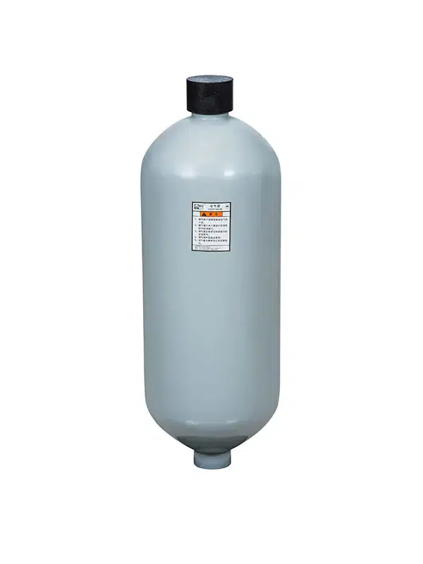
Accumulator is a key hydraulic component that stores energy, stabilizes system pressure, and improves the performance of hydraulic systems. Widely used in construction equipment, manufacturing machinery, agricultural machines, and industrial automation, hydraulic accumulators help increase efficiency, reduce system wear, and enhance operational safety. For manufacturers, suppliers, and wholesale buyers, understanding hydraulic components and their functions is essential for building reliable and efficient hydraulic systems.
Pumps, accumulator valves, and actuators need to work together for your system to perform efficiently. When valves respond steadily and cylinders move correctly, machines operate more safely and smoothly.
Engineering Safety Disclaimer: Hydraulic systems operate under extreme high pressure (often exceeding 350 Bar / 5,000 PSI). The formulas, parameters, and selection guidelines provided in this article serve as educational benchmarks for B2B procurement and system planning. All final circuit designs, component selections, and maintenance procedures must be validated by certified fluid power engineers in accordance with local safety regulations and specific original equipment manufacturer (OEM) manuals.
Fundamental Engineering Principles and Boundary Calculations
The mechanical synergy of all hydraulic components within a circuit is strictly governed by Pascal’s Principle. This physical law states that any pressure applied to a confined, incompressible fluid is transmitted completely and undiminished throughout the liquid. For B2B procurement engineers sizing system components, the foundational mathematical relationship is expressed as:
Pressure (p) = Force (F) / Area (A)
Where p represents the hydrostatic system pressure (measured in Pascals, N/m²), F represents the applied mechanical force (measured in Newtons), and A represents the effective cross-sectional surface area of the internal actuator piston (measured in square meters).
Field Application Calculation Example (With Boundary Conditions)
When procuring hydraulic cylinders for industrial automation—such as a heavy-duty industrial pressing jig—sourcing teams must calculate exact force outputs while factoring in mechanical friction and environmental limits.
- Given Target: An automated assembly line requires a dynamic linear cylinder to output a reliable working clamping force (F) of 150,000 Newtons.
- System Boundary Conditions: The system operates at a steady working pressure (p) of 21 MPa (21,000,000 Pascals). The ambient factory temperature is constant at 25°C, using ISO VG 46 mineral oil. An assumed mechanical efficiency of 90% is applied to account for cylinder seal friction (drag).
- Required Formula: Area (A) = [Force (F) / 0.90] / Pressure (p)
- Calculation: Area = [150,000 N / 0.90] / 21,000,000 Pa = 166,666.67 N / 21,000,000 Pa = 0.00793 square meters.
- Engineering Outcome: Based on this calculated area, solving for the diameter yields approximately 100.5 millimeters. The procurement team must select a standard catalog cylinder with a minimum internal bore diameter of 100 mm (or upsize to 110 mm) to safely achieve the required force without exceeding structural pressure limits.
Strategic Classification of Hydraulic Components
According to the international fluid power guidelines outlined in ISO 4413:2010 (Clause 5.4 – Control systems and components), industrial hydraulic components are systematically divided into three main functional categories. This rigorous classification ensures safety compliance and structural clarity during parts procurement.
| Functional Group | ISO 4413 Engineering Definition | Primary B2B Component Examples |
| Energy Converters | Components that convert external mechanical input into fluid power, or convert fluid power back into mechanical work. | Axial Piston Pumps, Heavy Gear Pumps, Linear Cylinders, Rotary Motors |
| Energy Controllers | Devices engineered to modify, throttle, switch, or direct the fluid’s pressure profile and total flow volume. | Solenoid Directional Valves, Proportional Flow Controls, Relief Valves |
| System Accessories | Passive elements that support overall circuit health, manage thermal loads, filter contaminants, and store energy. | Bladder Accumulators, Inline Suction Filters, Magnet Pots, Nitrile Seals |
Energy Converters: Technical Parameters and Testing Methodologies
Energy converters establish the base mechanical capacity of an industrial setup. Selecting the incorrect pump architecture leads to severe internal fluid shear, localized heat spikes, and premature failure.
Operational Parameters for Hydraulic Pumps
Pumps are active components responsible for generating fluid flow. Flow combined with system resistance generates pressure. Below are the standard operating pressure ranges and application environments for B2B procurement evaluation:
| Pump Architecture | Standard Operating Pressure Range | Baseline Application Environment |
| External Gear Pump | 150 Bar to 250 Bar (2,100 – 3,600 PSI) | Cost-effective industrial automation, agricultural tools, lubrication circuits. |
| Variable Vane Pump | 70 Bar to 160 Bar (1,000 – 2,300 PSI) | Low-noise indoor manufacturing, plastic injection molding, automated clamps. |
| Axial Piston Pump | 250 Bar to 400+ Bar (3,600 – 5,800+ PSI) | Heavy off-road vehicles, high-tonnage stamping presses, mining machinery. |
Volumetric Efficiency Baseline Data
Volumetric efficiency measures the ratio of actual fluid flow delivered versus the theoretical flow calculated from the pump’s physical displacement. The baseline efficiency metrics below are established via steady-state dynamometer testing (conducted at 50°C using standard ISO VG 46 mineral oil, simulating optimal continuous industrial operation).
| Converter Architecture | Documented Peak Volumetric Efficiency | Target Industrial Profile |
| Axial Piston Pump | ~95% | High-pressure closed-loop circuits where power density is critical. |
| Radial Piston Motor | ~95% | Heavy industrial winches and continuous high-torque wheel drives. |
| Gear Motor | ~85% | Low-pressure, cost-sensitive rotational machinery components. |
Energy Controllers: Precision Valve Regulation and Empirical Data
Valves act as the central control mechanism of the fluid power circuit. They ensure that high-pressure fluid flow is distributed safely in accordance with ISO 1219 circuit design schematics.
- Directional Control Valves: Serve as programmable fluid switches. By electrically or manually shifting an internal machined spool, they change fluid paths to extend cylinders or route fluid to the tank.
- Pressure Control Valves: Provide critical safety boundaries. Main relief valves are calibrated to crack open at a specific threshold (e.g., 10% above max operating pressure) to bypass fluid to the tank, preventing catastrophic hose bursts.
- Flow Control Valves: Regulate actuator speed by throttling the fluid volume (liters per minute) passing through the circuit.
Empirical Energy Savings: Industry testing in repetitive manufacturing environments (such as plastic injection molding cycles) demonstrates clear benefits from advanced flow controllers. Comparative field testing utilizing load-sensing proportional flow valves—as opposed to older fixed-displacement throttling methods—shows up to a 15% reduction in total electric motor energy consumption. Furthermore, eliminating unnecessary fluid throttling reduces average hydraulic oil operating temperatures by approximately 10%, directly extending fluid and seal lifespan.

System Accessories: Pressure Accumulators and Advanced Filtration
Passive accessories maintain system integrity, reduce moving component wear, and prevent unexpected machine shutdowns.
Structural Diagnostics of Pressure Accumulators
An accumulator is a specialized pressure vessel designed to store fluid energy. It uses a compressed inert gas (strictly Nitrogen, as oxygen poses a severe explosion risk under pressure) to push against the incompressible hydraulic fluid.
| Accumulator Design | Gas/Fluid Barrier | Engineering Advantage & Field Application |
| Bladder Type | Flexible Rubber Elastomer | Millisecond response times. Used for shock absorption in off-road vehicles managing varying UTV tire sizes and rough terrain. |
| Piston Type | Machined Metal Piston | Handles massive compression ratios. Standard for heavy industrial stamping presses and offshore oil tools. |
| Diaphragm Type | Welded Elastomer Membrane | Highly compact footprint. Ideal for localized pressure compensation and automotive braking circuits. |
Advanced Filtration and ISO 4406 Cleanliness
Particulate contamination causes over 75% of premature hydraulic component failures. Maintaining fluid cleanliness per ISO 4406 standards is mandatory. For instance, an ISO cleanliness code of 18/16/13 dictates strict limits on particles measuring 4, 6, and 14 microns per milliliter of fluid.
Beyond standard fiberglass mesh filters, advanced reservoirs incorporate magnetic filtration. Placing heavy-duty, rubber-coated magnet pots directly into the fluid reservoir tank allows the system to actively capture microscopic ferrous iron shavings. This isolates metal debris before it can circulate and score the highly polished internal valve spools.
Step-by-Step Engineering Selection Guide
To assist sourcing managers and fluid power engineers in making correct procurement choices, follow this strictly ordered component selection procedure:
- Determine Force and Boundary Limits: Calculate the total mechanical workload required by your actuators. Use the standard pressure formula, factoring in a 10% to 15% margin for mechanical seal friction and load variance.
- Select Energy Converters: Establish system pressure limits and required flow rates (L/min). Select a matching pump architecture (gear, vane, or piston) capable of delivering the flow without exceeding maximum temperature limits.
- Specify Safety and Control Valves: Match directional and flow valves to the maximum pressure capacity of your circuit. Ensure main system relief valves are integrated and set securely to prevent structural overload.
- Integrate Accumulators and Filtration: Choose bladder or piston accumulators based on required shock absorption speeds. Install return-line filters and magnetic reservoir traps to meet or exceed ISO 4406 baseline cleanliness codes.

Field Maintenance and Inspection Checklists
Routine maintenance must align with OEM specifications and international safety codes to prevent catastrophic pressure releases.
- Fluid Condition Analysis (Monthly): Extract oil samples to test for water contamination (indicated by milky viscosity) and conduct particle counts to ensure compliance with ISO 4406 targets.
- Nitrogen Pre-Charge Audits (Quarterly): Test accumulator gas pressure using specialized diagnostic manifolds. Operating an accumulator with a depleted nitrogen charge destroys the internal bladder and eliminates shock absorption.
- Seal and Wiper Audits (Weekly): Visually inspect linear cylinder rods for weeping fluid or scored metal, signaling early wiper seal degradation.
- Hose Safety Inspections (Pre-Operation): Inspect all external hydraulic hoses for abrasion, blistering, or fitting weeping in strict accordance with SAE J517 (100R-series specifications).
FAQ
What is the main purpose of a hydraulic accumulator?
A hydraulic accumulator stores pressurized fluid energy using compressed nitrogen gas and acts as a dynamic shock absorber. It supplements pump flow during high-demand cycles, maintains pressure when the pump is idle, and dampens violent pressure spikes that could otherwise rupture rigid piping.
How do engineers choose between a hydraulic pump and a motor?
They perform inverse tasks within the fluid power cycle. A pump converts mechanical energy (from an electric motor or diesel engine) into fluid flow and pressure. A hydraulic motor receives that pressurized fluid and converts it back into continuous mechanical rotational torque to spin machinery.
Why is empirical testing important for B2B component procurement?
Industrial environments have distinct physical limitations. Bladder accumulators, for instance, react instantly to pressure changes, proven by field data in mobile shock absorption. Purchasing decisions grounded in baseline efficiency data and ISO standards ensure the machinery meets strict safety, thermal, and load-bearing requirements.
References and Industry Standards
To maintain compliance and operational integrity, B2B procurement and engineering teams should refer to the following recognized industry standards when specifying hydraulic components:
- ISO 4413:2010 – Hydraulic fluid power — General rules and safety requirements for systems and their components.
- ISO 4406:1999 – Hydraulic fluid power — Fluids — Method for coding the level of contamination by solid particles.
- ISO 1219-1:2012 – Fluid power systems and components — Graphic symbols and circuit diagrams.
- SAE J517 – Hydraulic Hose Standard (Defines structural parameters for 100R-series industrial hoses).